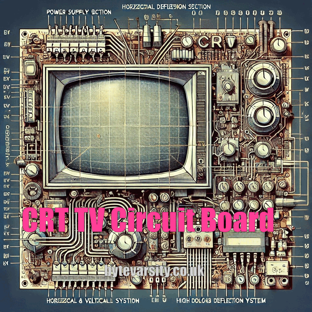
Introduction to CRT TV Circuit Boards
Cathode Ray Tube (CRT) TVs might seem like relics of the past, but to many technicians, they’re fascinating pieces of technology. These TV sets have a unique circuitry that, once understood, unlocks a whole new level of repair and maintenance knowledge. CRT TVs rely on electron beams and phosphor screens to create the image on the screen. Knowing how each part of the circuit board works makes all the difference when trying to fix that stubborn vintage TV.
Ever wondered why old TVs make that unique humming sound when turned on? It’s the high-voltage power supply kicking into gear—one of the many parts of a CRT circuit board that makes it so special. Understanding how these parts connect and interact is crucial for anyone diving into CRT repair.
How CRT TV Circuit Boards Work
CRT technology is all about electron beams shooting across a screen, lighting up phosphors to create an image. This process is orchestrated by the circuit board, which handles electron flow, image clarity, and color accuracy. If you’ve ever marveled at the sharpness of an old CRT screen, thank the circuit board for controlling those electron beams with such precision.
CRT TVs work with analog signals, making them a bit of a puzzle in today’s digital world. Unlike modern screens, which use digital inputs and direct pixels, CRTs rely on continuously moving beams. This analog signal control is what gives them their “old-school” charm but also makes them a challenge to repair. Without a solid understanding of the circuit board’s role, technicians might miss out on the full scope of CRT functionality.
Key Components of a CRT TV Circuit Board
Power Supply Section
The power supply in a CRT circuit board is like the engine of the TV. It provides the necessary voltage to all the circuits, keeping everything from the screen brightness to the audio levels in check. CRTs require a significant amount of power, which is regulated by transformers and circuits within this section.
Voltage transformers convert AC to DC and adjust it to suit the CRT’s needs. Without proper voltage, your TV won’t display a clear image or may fail to turn on entirely. If you’ve ever tried to turn on a CRT and heard a faint click but no picture, it’s often an issue with the power supply.
Horizontal and Vertical Deflection Systems
Deflection systems are essential for CRTs, as they control the path of the electron beam, forming the image across the screen. The horizontal deflection system guides the beam from side to side, while the vertical deflection system handles up and down movement. It’s this coordinated motion that creates a full image, one line at a time.
A malfunctioning deflection circuit can lead to image distortion or warping. Many technicians find that troubleshooting these sections requires patience, as they’re highly sensitive to even slight errors in voltage. Deflection circuits need to be spot-on for that classic CRT picture quality we all remember.
High Voltage (HV) Section
The high voltage (HV) section powers the CRT screen’s brightness by providing intense electricity to the tube. This section can produce up to 25,000 volts, so technicians must handle it with care. Ever seen a CRT with a dim or uneven display? It’s likely an HV issue, as high voltage is crucial for phosphor brightness.
Technicians take special precautions when working with HV components because mishandling this section can lead to electric shock. This is not the place for a casual “I’ll just poke around” approach; the HV section demands respect.

Common Issues and Troubleshooting CRT Circuit Boards
Diagnosing Faulty Circuits
CRT TVs can be tricky, especially with their analog nature. To diagnose issues, technicians often start with basic checks like capacitor integrity, which can deteriorate over time, leading to blurry images or color issues. Capacitors, resistors, and transistors are common culprits, as they tend to degrade faster in older TVs.
Tools like multimeters and oscilloscopes are invaluable for checking circuit functionality. Sometimes, technicians find surprises, like mouse nests or dust build-ups that disrupt current flow. Each CRT is like a puzzle waiting to be solved, and troubleshooting is a hands-on, immersive experience.
Diagnostic Tools and Techniques for CRT TV Repair
Multimeter Use
Multimeters are a technician’s best friend when testing continuity and voltage across circuits. By setting the multimeter to the correct range, you can identify short circuits or irregular voltages. A simple continuity test can sometimes reveal hidden issues, like a broken connection or failed capacitor, that otherwise go unnoticed.
Oscilloscope Testing
Oscilloscopes let technicians visualize signal paths within the CRT circuits. By observing waveforms, techs can pinpoint irregular signals, especially in the deflection and power supply sections. While an oscilloscope might seem high-tech, it’s essential for understanding a CRT’s analog signals and ensures technicians address the root problem rather than just treating symptoms.
Upgrading and Modifying CRT TV Circuit Boards
Performance Modifications
CRT enthusiasts often upgrade boards to boost picture quality or refresh colors. From tweaking color balance to adjusting signal frequencies, CRT mods can make a noticeable difference. However, maintaining the authenticity of a vintage CRT means balancing performance with classic aesthetics.
Conclusion: The Future of CRT Repair for Technicians
Despite newer technologies, CRT repair has its own fanbase. Understanding these circuit boards keeps CRTs alive and accessible. Whether for vintage gaming or preserving a piece of history, repairing CRTs is a skill worth mastering. The world may be digital, but the analog charm of CRT TVs continues to captivate, one circuit at a time.